In this article I will show you how to create a NE555 Timer IC based PWM DC Motor Speed Controller. I will share the circuit diagram, component list, tips for making the circuit yourself and a fully working Printable PCB Layout. You can fabricate your PCB with this layout and make the circuit easily. This is one of the most common circuits of my Electronics Hobby series.
Circuit Diagram of Motor Speed Controller
Following is a working circuit diagram of the NE555 PWM Based DC Motor Speed Controller.

How the Motor Speed Controller Works
In this circuit the NE555 timer IC is configured to generate square wave. The capacitor C2 gets changed and discharged through the output pin i.e. pin 3 of the NE555 timer. C2 charges through diode D1 and discharges through diode D2. The potentiometer VR1 (10K Ohm) defined the rate of charging and discharging thus the duty cycle of the PWM output.
The discharge pin i.e. pin 7 of the 555 timer IC is used to drive the MOSFET by generating PWM, instead of its usual purpose. It pulls down the MOSFET Gate during the discharge cycle of the circuit. The 1K resistor, during charge cycle pulls the MOSFET Gate back to high. Thus the MOSFET controls the speed of the motor, effectively driven by PWM Signal.
Note that there is a contradicting version of the circuit on the internet, where pin 3 and pin is just used the opposite way than how it is used in my circuit diagram. Rest assured that both of the circuits work. Pin 3 and Pin 7 of NE555 are almost equivalent to each other. The only difference is, pin 7 is an open-collector, while pin 3 has a totem-pole output. The 1K resistor is connected to pin 7, and it pulls up the MOSFET Gate to high, which eliminates any difference between pin 3 and pin 7.
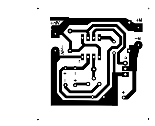
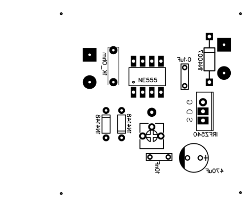
PCb Layout of Motor Speed Controller
The images shown below are scaled down to fit this page. Click on the images to open the actual-sized version of the PCB Layout images. Do not change the size of the images while printing. Alternatively you can use the printable PDF versions of the PCB Layout (download link given below these images).
Download the Printable PDF of NE555 based Motor Speed Controller PCB Layout
NE555 based PWM Speed Controller PCB Layout – Copper Side
NE555 based PWM Speed Controller PCB Layout – Top/Front Side
Buy the components required to make this circuit from an online electronic components shop and start making now! For any help, do not hesitate to contact me.
What’s the watt of the Motor ? Pls
The Motor which I tested with was 20 Watts. Continuous Drain Current of IRF540 is 28 Amp. Simple math suggests, at12 volt, it is expected to withstand a 336 watt motor’s load. But you need a BIG heat sink to apply such a huge load. But the PCB layout given here would not allow you to accommodate such a big heat sink, if you solder the MOSFET on the board. You have to connect the MOSFET with wires to the board to attach the heatsink.
Hi what is the value of VR1 ? Thanks
10K
what value is vr1?,its not marked!
Thanks for bringing into notice. Updated. 10K
Mr Bose.
What is a good value for VR1?
10K
also is C2 10nF or 10 uF? All other values are in uF , I am wondering
10nF (103)
Can i use 1N4007 in place of 1N4148?
Not ideally. In a PWM circuit, the frequency is usually on the higher side where a fast-switching diode like IN4148 is preferred over 1N4007.
Which software did you use for designing the PCB? Can you share the CAD files if it is ok with you? I want to replace the preset with a panel mountable pot. I want to use it for my PCB drill machine.
What do you want me to do with the CAD file?
Hi, thanks so much for this circuit. ¿Can I use this circuit to control a 12V Intel CPU fan? Thank you
Perhaps no because the CPU fan might be using a Brushless motor with 3 pins. Need to see the fan before confirming
What is the input voltage?
Can i plug in 20 volts?
Conventionally 6-12 volts. 20 volts will work too
Hi, I’m sorry to notice that this design do not work! The output of NE555 is on pin 3. This schematic get the square wave on pin 7… seem that the author have inverted pin 3 with pin 7.
This circuit does work. If you Google it you will plenty of examples generating PWM in this approach and the working principle is also explained. I have tested the circuit. It works 100%
Hi, can this circuit work to 24vdc motor?
No, you can’t simply apply 24V to this circuit to drive a 24V motor. 2 separate voltage needs to be used because NE555’s max input voltage is below 24V.
C3 is in the wrong location. Should be across dc supply.
Doesn’t hurt if you put another across the DC supply.
for C1 elco there is no positive and negative scheme please provide information. Thank sir…
C1 is a ceramic or polyester type capacitor. It doesn’t have positive/negative terminals. You can use a ceramic capacitor either way.